| What seems to be one of the most confusing
items related to the Automatic to 4 Speed tranmission swap is the
wiring. Lots of posts, many without picture, etc. So having gone
through more than a few tylenol during the process thought I would
give it a shot.
There are basically 3 areas you need to do some wiring:
I: Transmission/Engine Bay
II: Clutch pedal
III: Drivers
fenderwell
Note that some of the images, etc. are gathered from other posts.
My goal here was to have a single post that covers all 3 areas
instead of multiple posts, etc., etc. Credits to those who made the
posts, images, etc.
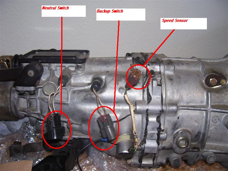
I: TRANMSISSION (Backup sensor, speed sensor and neutral
switch)
OK, you have removed the automatic transmission,
did not cut any of the wires connected to it, in other words you
disconnected the 3 connectors at the passenger side fender inside
the engine bay area by the HICAS solenoid (for TT models) and pulled
them down with the transmission.
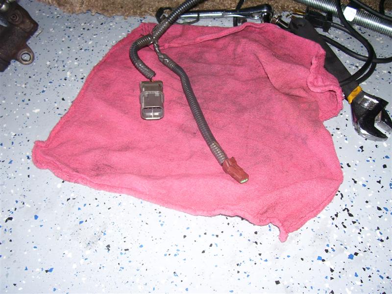
After removing the automatic transmission there will be two
connectors left dangling below the engine area.
The connectors left dangling on the right hand side coming
from the engine bay are pictured below
PICTURE
1
The brownish connector on the right goes to the speed sensor
connector on the manual transmission (see pic below for location
though not that hard as there is only one connector on the
transmission that fits).
The greyish connector on the left is not going to be used as it
went to the overdrive solenoid connector on the automatic. After all
is done simply wire tie it up out of the way.
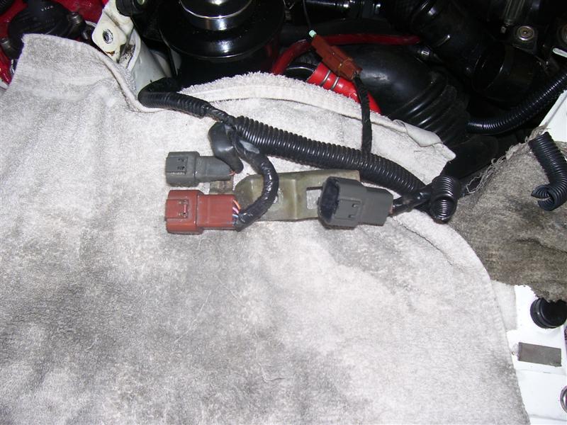
In the engine bay, above right hand fenderwell you will have the
below connections left over after you have removed the automatic
transmission harness with the transmission.
PICTURE
2
The two connectors on the left will not be used as they are
exclusive to the automatic transmission.
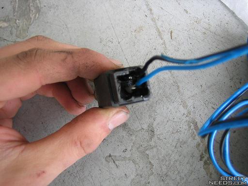
The connector on the right has two wires that will be used, they
are pins 4 and 7. Looking into the plug the numbering is:
1 2 3 4
5 6 7 8
Note that number 5 does not have a pin in it, make sure you take
note of this so that you have the orientation correct. This is
looking INTO the plug itself.
This connector will be used for the back-up/reverse lights and
connected to the sensor in the manual transmission.
PICTURE
3
Since only two of the wires in the connector at the right in
picture number 2 are going to be used you have two choices as
to how get them connected to the back up switch on the transmission
itself.
A. You can cut the connector off the harness that you pulled with
the automatic transmission and use it by splicing in some wire and
running it to the back up switch connector
-or do what I did which is:-
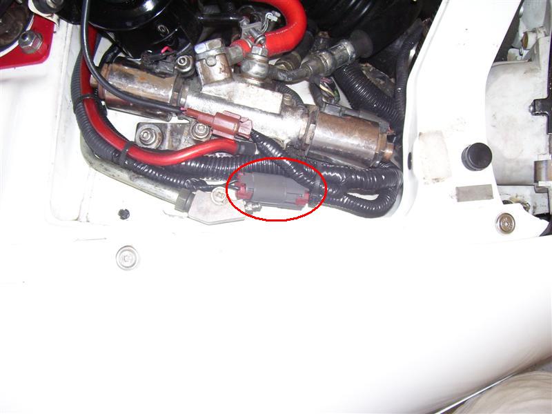
B. Cut both ends and solder directly to it a new connector with a
wire that you run to the back up switch or new connectors. Since I
had sold my automatic and did not therefore want to cut the
automatic harness I put on new connectors, see below.
The only thing I have not as yet figured out is where to connect
the wires from the neutral switch at the 5 speed. Note that it can
be left disconnected but I would rather leave that as an option to
others for the purpose of this document.
Picture 4 shows the connectors I soldered on, the
connectors are ones I got from YugoBernie. Note that I have also cut
the unnecessary connectors, wrapped them up with new tubing, etc.
Make sure that after you cut the wires that you cover each end with
heat shrink or electrical tape, do not want any unwanted grounds or
oddities!
Picture
4
II: Clutch pedal
Since the clutch pedal did not
exist prior and it has two connections you need to address that as
well. In all reality you could simply short the starter switch but
that means that you could start the engine without the clutch
engaged, not the best idea IMHO. The other switch is for the cruise
control cancel.
To make so that the cruise control disengages when the clutch is
depressed you will need to splice into the brake pedal cruise cancel
switch.
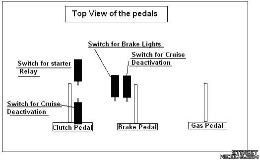
This
is the location of the switches. Your automatic car will not have a
connector for the Clutch pedals cruise switch so we need to tap into
the switch that is on the brake pedal closest to the passenger side.
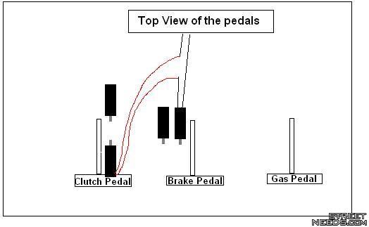
The
wiring will look like this. You must make certain to use the correct
type of switch (It should be black), the white switches will not
work. Its function is the opposite of what we need. Just make sure
the circuit is complete when the switches button is pushed in. The
easiest way to wire these in is to get some crimp on splices from
Radio Shack, the type that you put over a wire and crimp is what I
used.
III: Drivers fenderwell
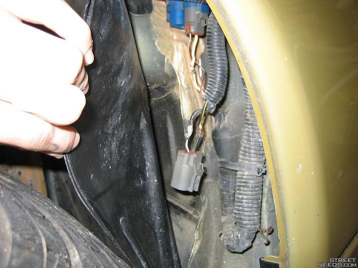
In
the driver fender the black/white and the black/yellow wires are the
ones that need to be connected. This will bypass everything. The
best thing to do is to wire the clutch pedal switch into these two
wires so that the starter only works with the clutch pedal pushed.
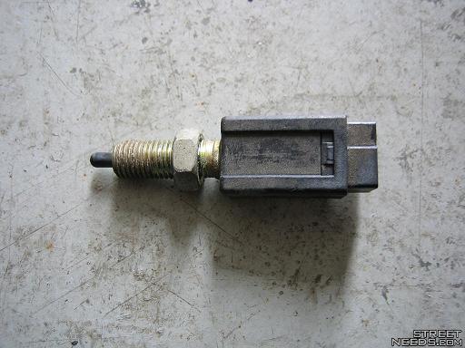
This
is the switch that is pushed when the clutch pedal is fully engaged.
It is nearest to the engine.
The
above is how Gold300ZX did it, instead of soldering as he did I
crimped on to the wires some shielded female spade connectors and
inserted them on to the pins. Easier IMHO.
Run the wire from the drivers fenderwell area into the passenger
compartment and connect to the switch on the clutch pedal, again, it
is the switch closest to the firewall.
Final notes
Undoubtedly you will have some other
issues, etc. to address. Some of the ones I ran into are:
~I used
a TT clutch booster with the TT clutch pedal. While you can use the
NA pedal, which eases installation quite a bit, I wanted the TT so I
could install the vacuum assist in the future. To install the TT
clutch booster and clutch pedal necessitates removal of the dash. A
lot of stuff to unscrew, etc. but not difficult at all. Took me all
of maybe 30 minutes. After you get it removed unbolt the steering
column to allow it to drop down a bit to ease installation.
IMPORTANT! there are FIVE bolts that hold the clutch pedal
assembly, 4 by the firewall and one at the top. YOU MUST bolt up all
5 or risk major issues.
~Clutch adjustment; most likely will need to do this. For info
see the post by
Greg Dupree here
~Clutch bleeding; probably the most important step, easy to do
but can be quite time intensive.
Thanks to one and all for all the help, IM's, phone calls, etc.!
CREDITS:
Gold300ZX for his post, some of which is
combined above, see http://twinturbo.net/net/viewmsg.aspx?forum=technical&msg_id=924769
_________________________________________________________________________________________

_________________________________________________________________________________________
Got
a Treo 650? Click
here for a Z skin for your Treo 650!
Background
on my Z
Check
out my parts for sale and parts I need! |


 Auto conversion to 5 speed wiring info -